1.Product Description
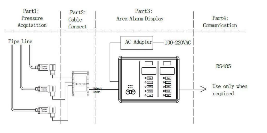
2.The whole medical gas area alarm system is including 4 parts as shown in the Diagram:
(1). Pressure Acquisition Part: Transmit the 4-20mA current signal that transformed by the gas pressure in the pipeline through the pressure sensor.
(2). Line Concentrator (cable connect part): collect all the cables of transmitters to one hub, and transmit pressure signal to the area alarm through an 8-core cable.
(3). Medical Gas Area Alarm Display Part: accept the signal from the hub, real-time monitoring each pipeline pressure.
(4). Communication Part: upload the monitored gas pressure and status to the upper machine by factory standard communication protocol.
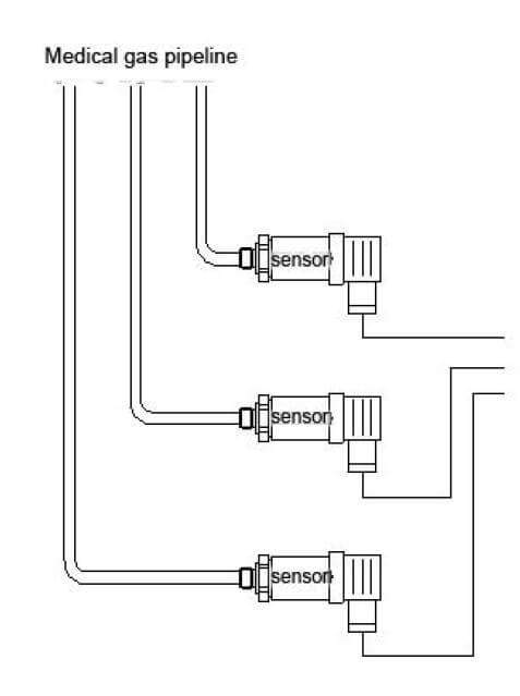
3.Pressure Pipeline Installation
As shown in the picture, the pressure pipeline collects the “pressure sensor” by the thread or quick coupling. Each pressure transmitter leads a 2-core cable, to transmit standard 4-20mA current signal, then to transmit pressure signal. Note: The total length of cables from hub to the medical gas area alarm could not be over 1000m. Over-length cables would reduce the strength of pressure signal and influence the accuracy of measurement. (The actual max length of cables depends on the working condition. )
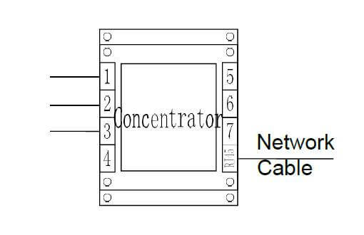
4.Line Hub Installation
As shown in the picture, the hub accepts the signals from the pressure transmitter. One hub can maximize to collect 7 pressure transducers.
The serial number on the hub(NO.1-7) relates to a port which is used to collect the pressure transducer. The number should be consistent with the one displaying in the area alarm. Eg. No.1 on the hub relates to “High-Pressure Alarm” in the left side of area alarm.
The total length of the hub input and output cables could not be over 1000m. Over-length cables would reduce the strength of pressure signal and influence the accuracy of measurement. (The actual max length of cables depends on the working condition. )
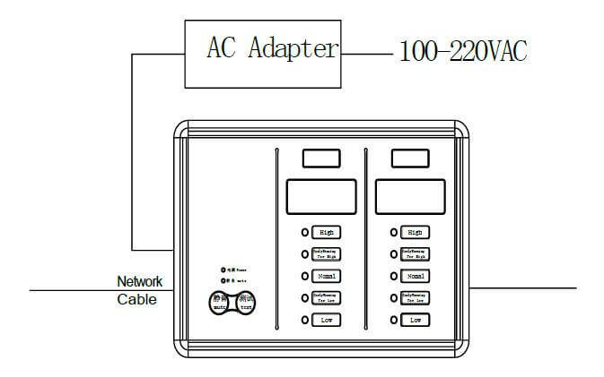
5.Area Alarm Installation
As shown in the picture, the medical gas area alarm only needs to collect the cables from the hub and AC adapter. It can work properly when the AC adapter
collects AC power 100-220V.
6.Working parameters adjustment
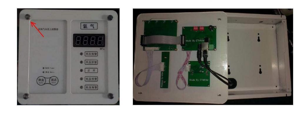
Remove the box
As shown in below picture, twist screws, located at the four corners of the box, can reveal the internal circuit board.
Note: the panel disassembly or after installation must restart it with electricity, may produce misoperation or touch button.
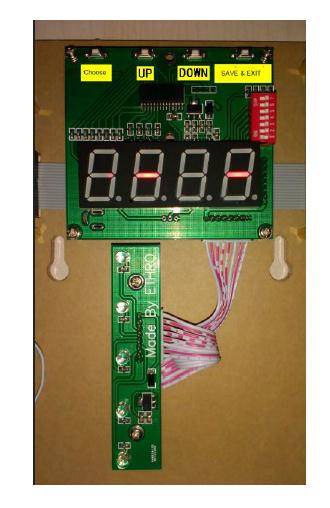
Button description
As shown in the picture, each gas relates to a list of the circuit board. There are four buttons on the circuit board: CHOOSE, UP, DOWN, Save and Exit.
CHOOSE: to switch the settings
UP: to up-regulate the parameter
DOWN: to down-regulate the parameter
Save and Exit: after setting all the parameters, save all the value, and then enter the working state.
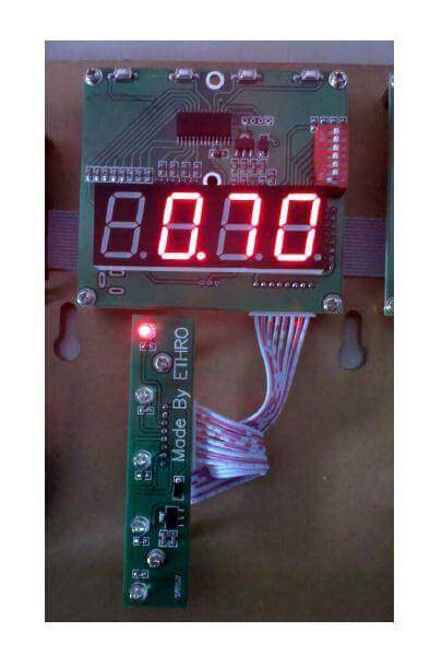
High-pressure alarm point setting
Instruction: when the gas pressure is equal or over the high-pressure alarm point, the alarm box will alarm in the audible and visual signal. Click “Selection”, when the first indicator lamp flash in high frequency, set the parameter by clicking “UP” or “DOWN”.
After setting, click “Selection” to set the other parameters or click “Save and Exit” to finish the setting. Factory defaults of high-pressure alarm point: Positive pressure: 0.7MP. Negative pressure: -0.02MPa.
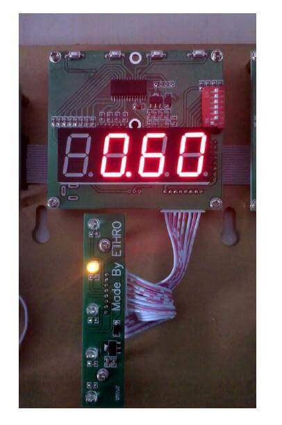
High-pressure pre-warning point setting
Instruction: when the gas pressure is equal or over the high-pressure warning point, the alarm box will warn with the flashing alarm light, no buzzer. Click “Selection”, when the second indicator lamp blink in high frequency, set the parameter by clicking “UP” or “DOWN”.After setting, click “Selection” to set the other parameters or click “Save and Exit” to finish the setting. Factory defaults of high-pressure pre-warning point: Positive pressure: 0.6MPa Negative pressure: -0.03MPa.
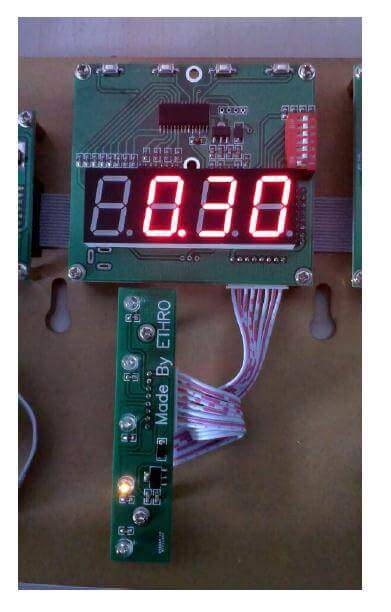
Low-pressure pre-warning point setting
Instruction: when the gas pressure is equal or lower than the low-pressure warning point, the alarm box will warn with the flashing alarm light, no buzzer. Click “Selection”, when the fourth indicator lamp blink in high frequency, then set the parameter by clicking “UP” or “DOWN”.After setting, click “Selection” to set the other parameters or click “Save and Exit” to finish setting. Factory defaults of low-pressure pre-warning point: Positive pressure: 0.3MPa Negative pressure: -0.1MPa.
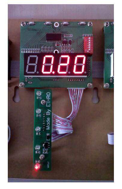
Low-pressure alarm point setting
Instruction: when the gas pressure is equal or lower than the low-pressure alarm point, the alarm box will alarm in the audible and visual signal. Click “Selection”, when the fifth indicator lamp blink in high frequency, set the parameter by clicking “UP” or “DOWN”. After setting, click “Selection” to set the other parameters or click “Save and Exit” to finish setting. Factory defaults of low-pressure warning point: Positive pressure: 0.2MPa Negative pressure: -0.11MPa.
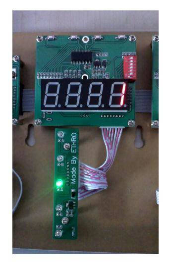
Column number setting
Instruction: assign the column number of the current circuit board, if the left is “NO.1”, it would be added up in turn to the right. The column number should be set correctly.
Click “Selection”, when the third indicator lamp blink in high frequency, set the parameter by clicking “UP” or “DOWN”. After setting, click “Selection” to set the other parameters or click “Save and Exit” to finish setting.
Factory settings already finished. No need for setting by the user.
7.Connector with master alarm
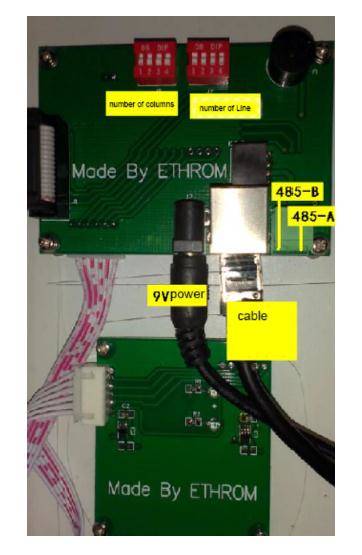
There are two dial switches at the backside of the alarm box, which are used to show the position of the area alarm on the master alarm. The sum of the number at the left dial switch is “column number”.The sum of the number at the right dial switch is “row number”.
There are two communication cables, “485-B” and ”485-A”. “485-B” of the area alarm should be connected to “485-B” of the master alarm. “485-A” of the area alarm should be connected to “485-A” of the master alarm. Then the system building finishes.
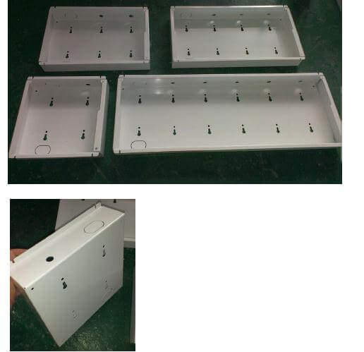
Medical Gas Area Alarm Outline Dimension Length*High*Thickness (mm)
ONE GAS TYPE 240*230*65
TWO GAS TYPE 340*230*65
THREE GAS TYPE 440*230*65
FOUR GAS TYPE 540*230*65
FIVE GAS TYPE 640*230*65
SIX GAS TYPE 740*230*65
SEVEN GAS TYPE 840*230*65
Medical Gas Area Alarm Preinstalled hole size Length*High*Thickness (mm)
ONE GAS TYPE 225*210*60
TWO GAS TYPE 325*210*60
THREE GAS TYPE 425*210*60
FOUR GAS TYPE 525*210*60
FIVE GAS TYPE 625*210*60
SIX GAS TYPE 725*210*60
SEVEN GAS TYPE 825*210*60